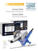
C4000 Photometric Converter

Multi Channel Photometric Converter

The C4000 converter is a multi channel controller capable of operating all optek photometric sensors. The C4000 converter allows for easy programming and operation, and can supply up to four real time configurable 4-20 mA output values correlated to any units of measure. The C4000 offers configurable relay alarms, can record and download process data, and can operate up to four sensors simultaneously.

    Used For

  • For UV, VIS, NIR Absorption sensors
  • Color scales:
    • APHA / HAZEN / Pt/Co color
    • AOCS (Method Cc 13b-45) color
    • ASTM (D1500) color
    • EBC color
    • ASBC color
    • Gardner (ASTM D1544) color
    • ICUMSA color
    • KLETT color
    • Reference Base Unit (RBU, color)
    • Saybolt (ASTM D 156, D 6045) color
  • Turbidity scales:
    • CU (concentration units)
    • ppm (DE)
    • FTU
    • NTU
    • FAU
    • EBC

The Control 4000 photometric converter is designed for optek ultraviolet (UV), visible (VIS), near-infrared (NIR) absorption based and scattered light based sensors. The graphic display can show absorbance, transmittance and concentration in real-time and in any unit of measure such as CU, OD, %-Tr., ppm (DE), EBC, FTU, g/L and many others.

Display Modes

  • 1 - 4 simultaneously displayed values (configurable)
  • Numeric with bar graph and alarm setting
  • Trendline
C4000 C8000

Remote Control

  • Parameter set (e. g. range)
  • Zero
  • Hold

Software Tools

  • 8 parameter sets (incl. range, alarm, display, etc.)
  • 16 linearization tables (max. 11 points)
  • 8 offset and slope sets
  • Auto zero (local or remotely activated)
  • Factory zero (scattered light sensors only)
  • Password protection (3 levels and none)
  • Memory (non-volatile) retains all configurations and logged data
Features
Benefits

4 channel photometric measurement converter and 2 signal inputs
Connect up to 4 photometric sensors and 2 analogue devices (e.g., pressure / temperature compensation in gas measurement)

Menu based software in serveral languages including linearization curve options
Easy configuration of the converter for individual applications

EX proof (ATEX, FM) housing and channels
Can be installed in hazardous areas saving additional installation costs

Graphics display for up to 4 real time measurements
Free editable measurement formats and multiple data display and output capabilities

Optional Profibus®PA and FOUNDATION™Fieldbus connectivity
Easy implementation of data communication into Bus-Environment
C4000
Housing

19"-version for mounting in control cabinets 3 U / 42 HP

dimensions:W 213.0 mm (8.39 in.) H 128.4 mm (5.06 in.) D 230.0 mm (9.05 in.)

material:stainless steel / polyester / silicone / glass / diverse plastics

protection:front IP40 / rear IP20 (mains supply secured against accidental touching)

Display

LCD graphic display black on white (240 x 128 pixel), LED background illuminated

Operation

18-button keyboard

System clock

accuracy approx. 1 minute/month (battery life approx. 15 years)

LED

1 LED (green):power on

1 LED (red-flashing):system failure

3 LEDs (yellow):alarm I, II, III

Data logger

4 parallel measuring values

(ring buffer with approx. 25,000 data points x 4)

(interval: 1/second - 1/hour)

Sensor-inputs

1 - 4 for optek photometric sensors

Sensor-inputs
(explosion proof)

optional:1 - 4 for optek photometric sensors (intrinsic safe)

mA-inputs

optional:

2 x 4 - 20 mA (functionally galvanically isolated)

accuracy: < 0.5 %

resolution: < 0.05 %

load: < 200 Ohm

Remote-inputs

optional:7 x 24 V (19 ... 29 V DC),
typically 6.0 mA for remote range setting, remote zero, remote hold

Profibus® PA interface

optional:

Profibus® PA profile, version 3.01, amendment 2

FOUNDATION™ Fieldbus interface

optional:

FOUNDATION™ Fieldbus H1 (IEC 61158-2)

Sensor lamp-outputs

1 or 2 lamp supply for optek photometric sensors

4.5 ... 8.5 V DC

mA-outputs

2 or 4 x 0/4 - 20 mA (NAMUR)

(functionally galvanically isolated)

accuracy: < 0.5 %

resolution: < 0.05 %

load: < 600 Ohm

Relay-outputs

3 independent software-configurable relay contacts

0 - 50 V AC, 0 - 75 V DC, 0 - 2 A

for alarm or status feedback

initiation delay configurable: 0 - 999 sec.

Failsafe-output

1 SPDT contact to alarm in case of lamp or system failure (active)

0 - 50 V AC, 0 - 75 V DC, 0 - 2 A

Serial communication

RS232 bi-directional interface on front panel (with software package optek PC-transfer)

upload / download of configuration, download of data logger content

Cable lengths
(sensor)

2, 3, 5, 10, 15, 20, 30 ... 100 m

(7, 10, 16, 33, 49, 66, 98 ... 328 ft)

cable length > 100 m on request up to 1,000 m (3,280 ft)

sensors: AS56 / AS16: max: 50 m

sensors: ASD: 2, 3, 5 or 10 m (7, 10, 16 or 33 ft.)

Power supply

115 / 230 V AC, selectable (93.5 - 132 / 187 - 264 V AC, 47 - 64 Hz) or 24 V AC / DC (AC: 20.4 - 26.4 V AC, 47 - 64 Hz; DC: 20.4 - 28.8 V DC)

power consumption:< 50 VA

Ambient conditions

temperature during operation (no direct sunlight):

converter: -10 - 55 °C (14 - 131 °F)

with optional stainless steel housing S19-42 (IP65): -20 - 45 °C ( -4 - 113 °F)

with optional plastic housing B19-42 (IP66): -10 - 40 °C (14 - 104 °F) (C4000 only)

with optional Ex D housing (IP65): -20 - 40 °C ( -4 - 104 °F) (C4000 only)

temperature during transport (no direct sunlight): -20 - 70 °C ( -4 - 158 °F)

Software languages

English, German, French, Spanish, Dutch, Portuguese, Russian

Data given are subject to changes without prior notice.
Sensor C4000 Configurations
1 2 3 4 4101 4121 4151 4161 4201 4221 4251 4261 4202 4222 4252 4262 4422 4452 4462
AF16 (AS16) - - - checkmark checkmark checkmark checkmark
AF16 (AS16) AF16 (AS16) - - - - checkmark checkmark
AF16 (AS16) AF26 or AF45 or TF16 - - - - - checkmark
AF26 - - - - checkmark checkmark checkmark
AF26 AF26 or AF45 or TF16 - - - - - checkmark
AF45 - - - - checkmark checkmark checkmark
AF45 AF45 or TF16 - - - - - checkmark
AF46 - - - - - - checkmark
TF16 - - - - checkmark checkmark checkmark
TF16 TF16 - - - - - checkmark
ASD12 or ASD25 - - - checkmark checkmark checkmark checkmark
ASD12 or ASD25 ASD12 or ASD25 - - - checkmark checkmark checkmark
ASD12 or ASD25 ASD12 or ASD25 ASD12 or ASD25 - - - - checkmark
ASD12 or ASD25 ASD12 or ASD25 ASD12 or ASD25 ASD12 or ASD25 - - - checkmark
C4000 Back panel
C4000 Configurations 4101 4201 4202 4121 4221 4222 4422
1 Detector inputs (optek) 1 2 2 1 2 2 4
2 Power supply 115/230 or 24 V checkmark checkmark checkmark checkmark checkmark checkmark checkmark
3 Remote-IN: (Zero, Range, Hold) - - - checkmark checkmark checkmark checkmark
4 Relay-outputs 3 3 3 3 3 3 3
Failsafe-relay (active) checkmark checkmark checkmark checkmark checkmark checkmark checkmark
5 Lamp output (optek) 1 1 2 1 1 2 2
6 mA-outputs (0/4 - 20 mA) 2 2 4 2 2 4 4
7 mA-inputs (4 - 20 mA) - - - 2 2 2 2
pH-probe - (with C8000/C800 only)
Conductivity (optek ACF/ACS) - (with C8000/C800 only)
Ex-proof (optional) checkmark checkmark checkmark checkmark checkmark checkmark checkmark

PROFIBUS® PA

  • Fulfills application profile for process automation (version 3.01)
  • Cyclic:
    • 4 measuring outputs, each with 4x limit and status
    • Status of all 4 relays
    • 2 measuring inputs
  • Acyclic:
    • Zero, Hold, Product change, Monitors, Error codes
  • GSD, EDD file and DTM for FDT interface provided
  • Interface to profibus DP segment using a segment coupler

FOUNDATION™ Fieldbus

  • Fulfills FOUNDATION™ Fieldbus H1 (IEC 61158-2)
  • Registered function blocks: 1xRB, 8xAI(s), 4xDI(s), 2xAO(s)
  • H1 Profile class: 31P, 32L
  • H1 Device class: basic, link master
  • 4 Measuring outputs with status (C8000 8 measuring outputs with status)
  • 4 Relays with status (C8000 1 Relay with status)
  • 2 Measuring inputs (only C4000)
  • With optek specific resource block parameter: Zero, Hold, Product change
  • Device description (DD) and capabilities files provided
C4000 PROFIBUS Back panel
C4000 Configurations
8 PROFIBUS® PA 4151 4251 4252 4452
FOUNDATION™ Fieldbus 4161 4261 4262 4462
1 Detector inputs (optek) 1 2 2 4
2 Power supply 115/230 or 24 V checkmark checkmark checkmark checkmark
3 Remote-IN: (Zero, Range, Hold) - - - -
4 Relay-outputs 3 3 3 3
Failsafe-relay (active) checkmark checkmark checkmark checkmark
5 Lamp output (optek) 1 1 2 2
6 mA-outputs (0/4 - 20 mA) 2 2 4 4
7 mA-inputs (4 - 20 mA) - - - -
pH-probe - (with C8000/C800 only)
Conductivity (optek ACF/ACS) - (with C8000/C800 only)
Ex-proof (optional) checkmark checkmark checkmark checkmark

Speed / Spare Parts

Installation Kit C4000 PN: 1200-3321-0009-00

Installation Kit C4000

PN: 1200-3321-0009-00

Installation Kit S19 PN: 1200-3390-0003-00

Installation Kit S19

PN: 1200-3390-0003-00

Installation Kit B19 PN: 1200-3390-0001-00

Installation Kit B19

PN: 1200-3390-0001-00

Front panel Mounting Kit for series C4000, C8000, HazeControl PN: 1200-3321-0001-00

Front panel Mounting Kit for series C4000, C8000, HazeControl

PN: 1200-3321-0001-00

Wall mount housing B19-42 for 1 converter C4000, HazeControl or for 2 converters X56 PN: 1200-3321-0002-00

Wall mount housing B19-42 for 1 converter C4000, HazeControl or for 2 converters X56

PN: 1200-3321-0002-00

Wall mount housing S19-42 for 1 converter C4000, C8000, HazeControl or for 2 converters X56 PN: 1200-3321-0003-00

Wall mount housing S19-42 for 1 converter C4000, C8000, HazeControl or for 2 converters X56

PN: 1200-3321-0003-00

10x Fuse T 1,600A (5x20)   PN: 1200-3300-0005-00

10x Fuse T 1,600A (5x20)

PN: 1200-3300-0005-00

10x Fuse T 3,150A (5x20)   PN: 1200-3300-0007-00

10x Fuse T 3,150A (5x20)

PN: 1200-3300-0007-00

C4000 - C8000 Product Information

Visit our documentation page to view a complete list of translated documents.