How does the number of electrodes and poles effect conductivity measurements?
Two-electrodes, two-pole design
The simplest sensor is based on the traditional two-electrodes, two-pole design. Here the current entry and voltage measurement are realized using the same pair of electrodes. Since at high conductivities the voltage drop at the electrodes (ZTransition) and in the cable (ZCable) becomes relatively big compared to the voltage drop in the medium (Rmedium), the two-pole design is only suitable for low conductivities (typically 1 µS up to 500 µS).
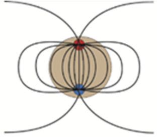
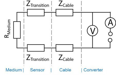
Figure 1 & 2: electric field lines around a 2 pole sensor and the equivalent circuit diagram
Four-electrodes, four-pole design
The separation of current-inducing and voltage-measuring electrodes almost completely eliminates polarization issues and the influence of the cable resistance. However, the capacitive influence of the cable remains and has to be compensated. Due to the inhomogeneity of the electric field at the voltage electrodes, the cell constant of a four-pole system is strongly influenced by the conductivity of the solution. I.e., transmitters working with a four pole cell offer the input of different cell constants to cover the whole conductivity range.
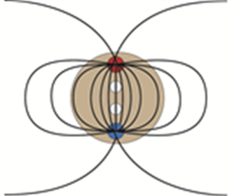
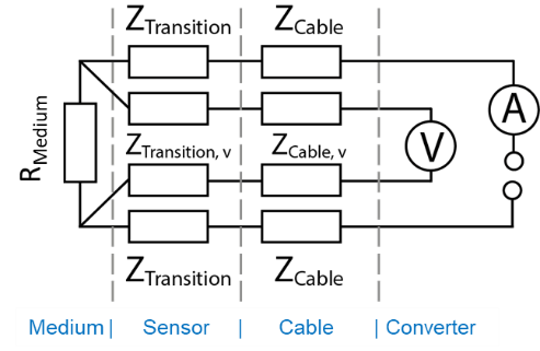
Figure 3 & 4: electric field lines around a 4 pole sensor and the equivalent circuit diagram
Six-electrodes, four-pole design
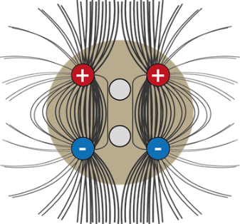
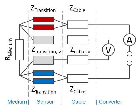
In a six pole design, the current entry is realized using two electrodes per pole. While the corresponding electrical circuit is identical to the four-electrode, four-pole design, the big difference lies in the strength and homogeneity of the electrical field present at the voltage measuring electrodes. The more homogeneous field distribution in the area of the voltage electrodes results in a much less variable cell constant, since the influence of the fringe effect is drastically reduced. In addition the 6-electrode 4 pole design allows for a much higher field density and less sensitivity to field distortion.
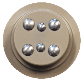
ACF60 conductivity sensor, 4-poles and 6 electrodes
Figure 5 & 6: electric field lines around a 6 electrode 4 pole sensor and the equivalent circuit diagram
Read more on optek's unique Six-electrode, Four-pole Design
Get in Touch with optek

- Germany
- +49-(0)201-63409-0
- United States
- +1-262-437-3600
- Singapore
- +65-6562-8292
- China
- +86-21-28986326