Introduction
Any particle distributed in a liquid can absorb and scatter light, depending on the particle size. The particle size may be smaller or larger than the wavelength of the light source. In case of the particles are smaller the effect is called Opalescence, if they are larger, it is called Opacity or Haze.
For precise detection of any particles causing the turbidity or haziness, a sensor should combine a durable and stable light source with three detectors positioned at 0°, 11° and 90° to the light beam. While 0° transmission is used as reference for general light absorption (e.g., based on sample coloration), the 11° light scatter signal intensity identifies larger particles and with 90° light scatter smaller particles are detected. In addition, the 90° angle fulfils the DIN EN ISO norm 27888, EPA 180.1 requirements for nephelometric measurements.
Why use an 11° measurement?
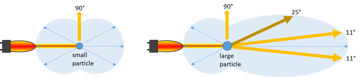
Figure 2: best optical angles to detect individual particles
Forward scattered light is particle size sensitive and its strength is in detecting particles such as yeast, trub and Kieselguhr, efficiently detecting filter breaks and filtrate turbidity caused by particles, even at extremely low concentrations. Measurements at 11° are very sensitive in this regard and correlate well to actual non-dissolved solids content, essential for proper filtration control and optimization.
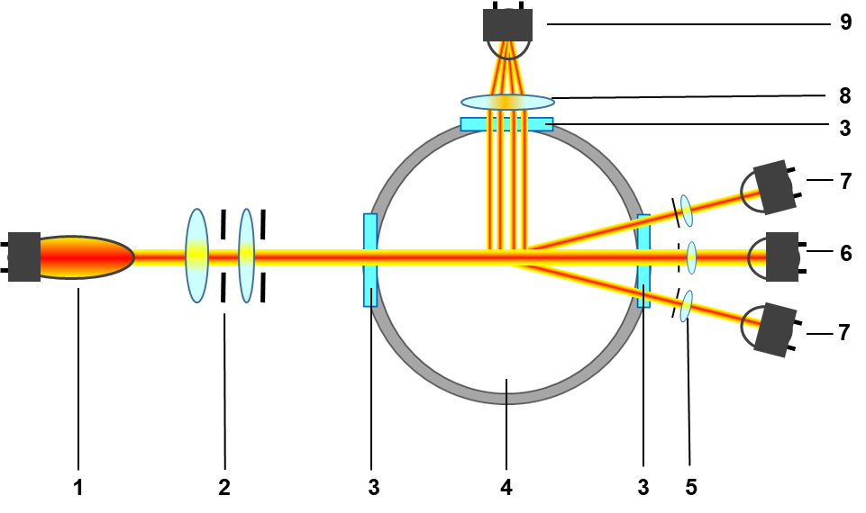
Figure 1: optical and detector setup of the optek DTF16 sensor
- lamp module (VIS NIR)
- optics module
- optical windows
- sensor body
- optics module forward scatter
- detector (0°)
- detector (11°)
- optics module side scatter
- detector (90°)
Why is 11° better than the 25° measurement?
Scattered light at 11° is more specific due to a higher signal and will detect abnormal particulate faster without the influence from colloidal material common at e.g., 25°. This also aids in the prompt troubleshooting of filtration problems.
Why use a 90° measurement?
Turbidity measurements at an angle of 90° are highly sensitive to colloids and are used as a quality check for the clarity of the beer. Mistakenly, 90° techniques have been used for process evaluations but do not correlate to actual non-dissolved solids content. Modern breweries can now measure this parameter inline and thus provide the ability to release beer automatically.
Why use a 0° absorption measurement?
Using the 0° absorption channel allows measurements at higher turbidity levels, well beyond the range of the 11° or 90° results, allowing you to monitor and control the filter pre-coat cycle as well. This provides an additional opportunity for filter optimization.
Factory Calibration and Zero Point
The power behind the optek Haze Control DTF16 is the factory zero point. No longer is a questionable zero media (e.g., process water) or offline zero procedure required. Using known technical reference solutions and purest zero media, optek developed a factory calibration with a precise zero point. The drift-free factory zero point eliminates the need for regular zeroing of the instrument saving you time and money and does not depend on the operator. It also ensures that every instrument is base lined identically and precisely. This is invaluable when relying on multiple instrument locations.
Every optek Haze Control DTF16 is factory calibrated to EBC standards, which correlate to all other standards currently in use in process plants today. This calibration is stable for the life of the sensor and does not need recalibration, providing a low cost of ownership. This ensures precise, repeatable and reliable measurements across multiple instruments and locations.
Drift-free by Design
Baseline drift of scattered-light sensors has long been a problematic issue. This is usually caused by unwanted scattered-light, stray light from reflections in the sensor assembly, from the light source itself, worn artificial coatings or external light (i.e., sight glasses). This stray light influences the measurement in an unpredictable fashion. The optek DTF16 incorporates advanced geometry to eliminate this problem by re-directing the stray light away from the detectors. This design does not rely on any coatings and maintains a cleanable, sanitary design.
DTF16 sensor typical applications
- Activated Carbon as particles
- Centrifuge Control
- EBC Turbidity
- Filter control
- Oil in Water
- Water Quality
- Separator control
- Suspensions, Suspended Solids
- Turbidity (e.g. FTU, EBC, ppm)
- Yeast
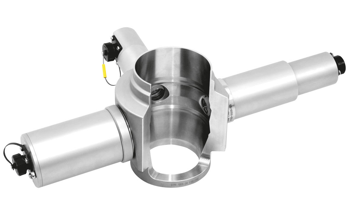
Figure 3: DTF16 sensor
Filtration Control
Filtration is one of the most important steps in the brewing process. The optek Haze Control DTF16 allows you to measure and control this crucial process and provides real-time quality assessment. In addition to releasing beer by instrument, there are tremendous opportunities to reduce beer loss, media usage and production costs while increasing filtration capacity and ensuring consistent product quality.
optek Haze Control Converter
With the legendary optek Haze Control signal amplification stability, the DTF16 dual beam ratio detectors and advanced Haze Control firmware and you get a drift and calibration-free process turbidity analyzer with exceptional long-life performance.
Designed for ease of use, the Haze Control has a built in data logger providing you with continuous trending. This data can be displayed locally and uploaded to a computer, allowing production personnel to review process inconsistencies or any historical process issues.
The Haze Control offers multiple communication options. Up to four mA-outputs can be used simultaneously to transmit data or completely control the converter remotely using a standard I/O interface. Also the bus communication PROFIBUS® PA or FOUNDATION™ Fieldbus is available to integrate the system optimally in your PLC system.
Thanks to the four-channel design of Haze Control, the DTF16 three channel haze sensor can be combined with a one-channel sensor, such as AS16-F colour sensor or AS16-N turbidity sensor.
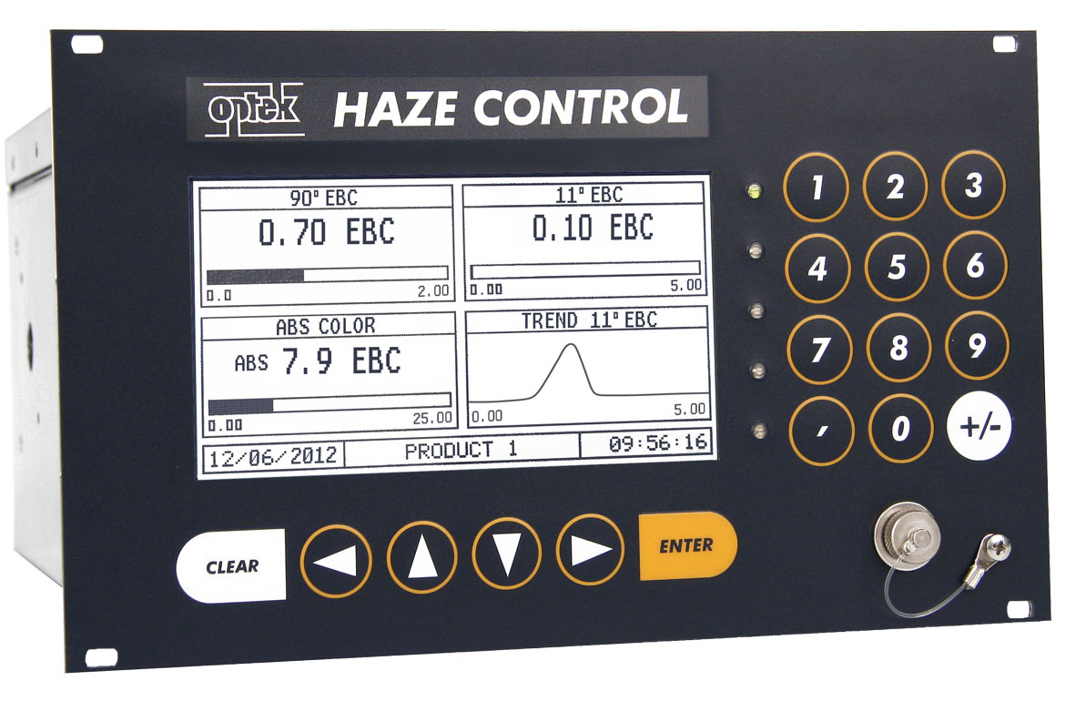
Figure 4: Haze Control Converter
Example: the Haze Control / DTF16 system measures simultaneously after the filter:
- the colloidal turbidity / haze (quality parameters)
- the breakthrough of yeast or filter aid (with Kieselguhr filter).
and can be combined with a second sensor in the filter inlet:
- NIR Sensor: monitoring of filter backwash processes
- Color sensor: monitoring of product changes (beer-water separation)
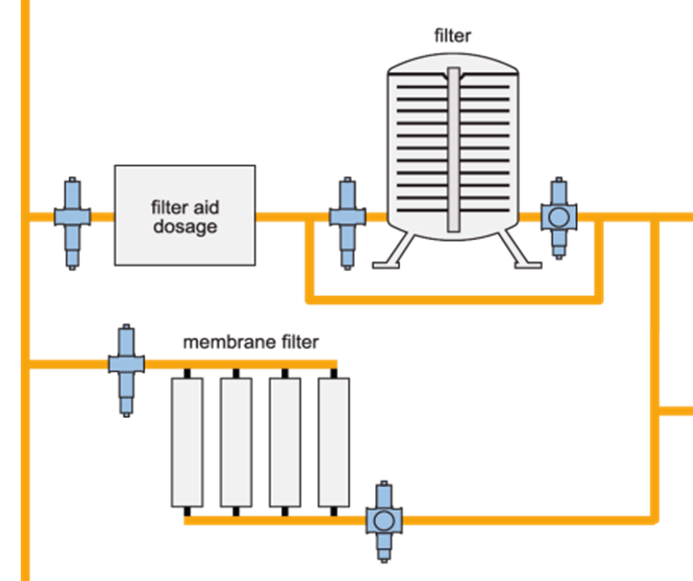
Figure 5: schematics of the beer filter process and optimized process control measurement
Get in Touch with optek

- Germany
- +49-(0)201-63409-0
- United States
- +1-262-437-3600
- Singapore
- +65-6562-8292
- China
- +86-21-28986326